AADL tutorial - part 1
About AADLv2
The “Architecture Analysis and Design Language” AADL is a textual and graphical language for model-based engineering of embedded real-time systems. It has been published as an SAE Standard AS5506B. AADL is used to design and analyze the software and hardware architectures of embedded real-time systems.
AADL allows for the description of both software and hardware parts of a system. It focuses on the definition of clear block interfaces, and separates the implementations from these interfaces. It can be expressed using both a graphical and a textual syntax. From the description of these blocks, one can build an assembly of blocks that represent the full system. To take into account the multiple ways to connect components, the AADL defines different connection patterns: subcomponent, connection, and binding.
An AADL model can incorporate non-architectural elements: embedded or real-time characteristics of the components (such as execution time, memory footprint), behavioral descriptions. Hence it is possible to use AADL as a back- bone to describe all the aspects of a system. Let us review all these elements:
An AADL description is made of components. The AADL standard defines software components (data, thread, thread group, subprogram, process) and execution plat- form components (memory, bus, processor, device, virtual processor, virtual bus) and hybrid components (system). Each Component category describe well identified elements of the actual architecture, using the same vocabulary of system or software engineering:
-
Subprograms model procedures like in C or Ada.
-
Threads model the active part of an application (such as POSIX threads). AADL threads may have multiple operational modes. Each mode may describe a different behavior and property values for the thread.
-
Processes are memory spaces that contain the threads. Thread groups are used to create a hierarchy among threads.
-
Processors model microprocessors and a minimal operating system (mainly a scheduler).
-
Memories model hard disks, RAMs, buses model all kinds of networks, wires, devices model sensors, …
-
Virtual bus and Virtual processor models “virtual” hardware components. A virtual bus is a communication channel on top of a physical bus (e.g. TCP/IP over Ethernet); a virtual processor denotes a dedicated scheduling domain inside a processor (e.g. an ARINC653 partition running on a processor).
Unlike other components, Systems do not represent anything concrete; they combine building blocks to help structure the description as a set of nested components.
Packages add the notion of namespaces to help structuring the models. Abstracts model partially defined components, to be refined during the modeling process.
Component declarations have to be instantiated into subcomponents of other components in order to model system architecture. At the top-level, a system contains all the component instances. Most components can have subcomponents, so that an AADL description is hierarchical. A complete AADL description must provide a top-most level system that will contain certain kind of components (processor, process, bus, device, abstract and memory), thus providing the root of the architecture tree. The architecture in itself is the instantiation of this system, which is called the root system.
The interface of a component is called component type. It provides features (e.g. communication ports). Components communicate one with another by connecting their features. To a given component type correspond zero or several implementations. Each of them describes the internals of the components: subcomponents, connections between those subcomponents, etc.
An implementation of a thread or a subprogram can specify call sequences to other subprograms, thus describing the execution flows in the architecture. Since there can be different implementations of a given component type, it is possible to select the actual components to put into the architecture, without having to change the other components, thus providing a convenient approach to configure applications.
The AADL defines the notion of properties that can be attached to most elements (components, connections, features, etc.). Properties are typed attributes that specify constraints or characteristics that apply to the elements of the architecture: clock frequency of a processor, execution time of a thread, bandwidth of a bus, . . . Some standard properties are defined, e.g. for timing aspects; but it is possible to define new properties for different analysis (e.g. to define particular security policies).
AADL is a language, with different representations. A textual representation provides a comprehensive view of all details of a system, and graphical if one want to hide some details, and allow for a quick navigation in multiple dimensions. In the following, we illustrate both notations. Let us note that AADL can also be expressed as a UML model following the MARTE profile.
The concepts behind AADL are those typical to the construction of embedded systems, following a component- based approach: blocks with clear interfaces and properties are defined, and compose to form the complete system. Besides, the language is defined by a companion standard document that documents legality rules for component assemblies, its static and execution semantics.
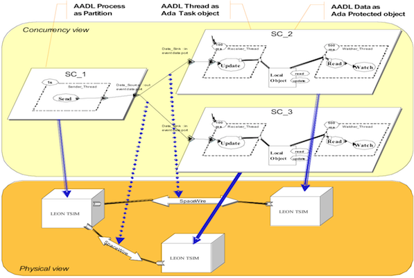
The following figure illustrates a complete space system, used as a demonstrator during the ASSERT project. It illustrates how software and hardware concerns can be separately developed and then combined in a complete model.
